Web ac single phase motors part 2 magnetic starter wiring an allen bradley 709 3 for 220v the hobby machinist vfd diagram showing power in out and control device. It is a 2hp, single phase, 120/240 dual voltage motor. Web this type of motor is used in many applications, from powering ceiling fans to running compressors.
120 240 Wiring Diagram Knit Fit
Web the 120 240 motor wiring diagram is an important tool in understanding the inner workings of an electrical appliance. Web a 120 240 motor wiring diagram is a drawing that shows all of the connections between the motor’s components. Web the motor has a split stator coil that allows for 120v or 240v connection.
U1, U2, U5, V1, V2, V5, Blue(Not Numbered).
Web this page includes details on the 120/240 volt motor wiring diagram, hints, and frequently asked questions. Web a 120/240 motor wiring diagram shows you how to connect the power source and other electrical components to the motor. It is important to understand the wiring diagram so that you can.
This Motor Has 8 Wires.
Web what is a 120/240 volt motor wiring diagram? Web south bend lathes first of a few question new sb 9 owner wiring questions practical machinist largest manufacturing technology forum on the web need help old. It includes the motor’s power source,.
Web 4 Pole Single Phase Ac Motor Wiring Electric Motors Generators Engineering Eng Tips.
A 120/240 volt motor wiring diagram is a simplified schematic representation of an electric motor’s wiring. Web we have a submersible motor. 2 kva transformer primary 240x480.
This Visual Representation Of The Wiring Makes It Easy To Identify The Different.
He had the following wires coming out of the motor twisted. Web i have attached photos of the the motor wiring diagram and the 3 wires that are hanging out of the saw. It shows the connection between the different.
We Produced This Page To Help Those Trying To Find.
Web understanding the 120/240 volt motor wiring diagram september 28, 2022 when dealing with an electric motor, understanding the wiring diagram is. Web when looking at a wiring diagram for a 240 volt electric motor, it is important to understand the symbols which are used in the diagram.these symbols. This diagram provides detailed information.
Web It Was Left With No Diagrams.
The black wire is a mains lead, and has a thermal overload switch on it (the weird symbol on. Web if the motor has a dual voltage capability then it will state 120/240 volts, and there will be a wiring configuration or wiring connection diagram which will explain the wiring. Web a wiring diagram is a straightforward visual representation in the physical connections and physical layout of the electrical system or circuit.
Magnetic Starter Wiring An Allen Bradley 709 3 Phase For Single 220V The Hobby Machinist Motor.
Web the most common type of 120/240 volt motor wiring diagram is the ladder diagram.

120/240 Volt Motor Wiring Diagram

120 240 Motor Wiring Diagram Wiring Diagram

120 240 Wiring Diagram Knit Fit

Switching a motor between 240 and 120 volts

How to Wire 120V & 240V Main Panel? Breaker Box Installation
480 Volt 3 Phase Motor Wiring Diagram 120 240 Volt Motor Wiring

240v AC single phase to 120/240 split phase Victron Community

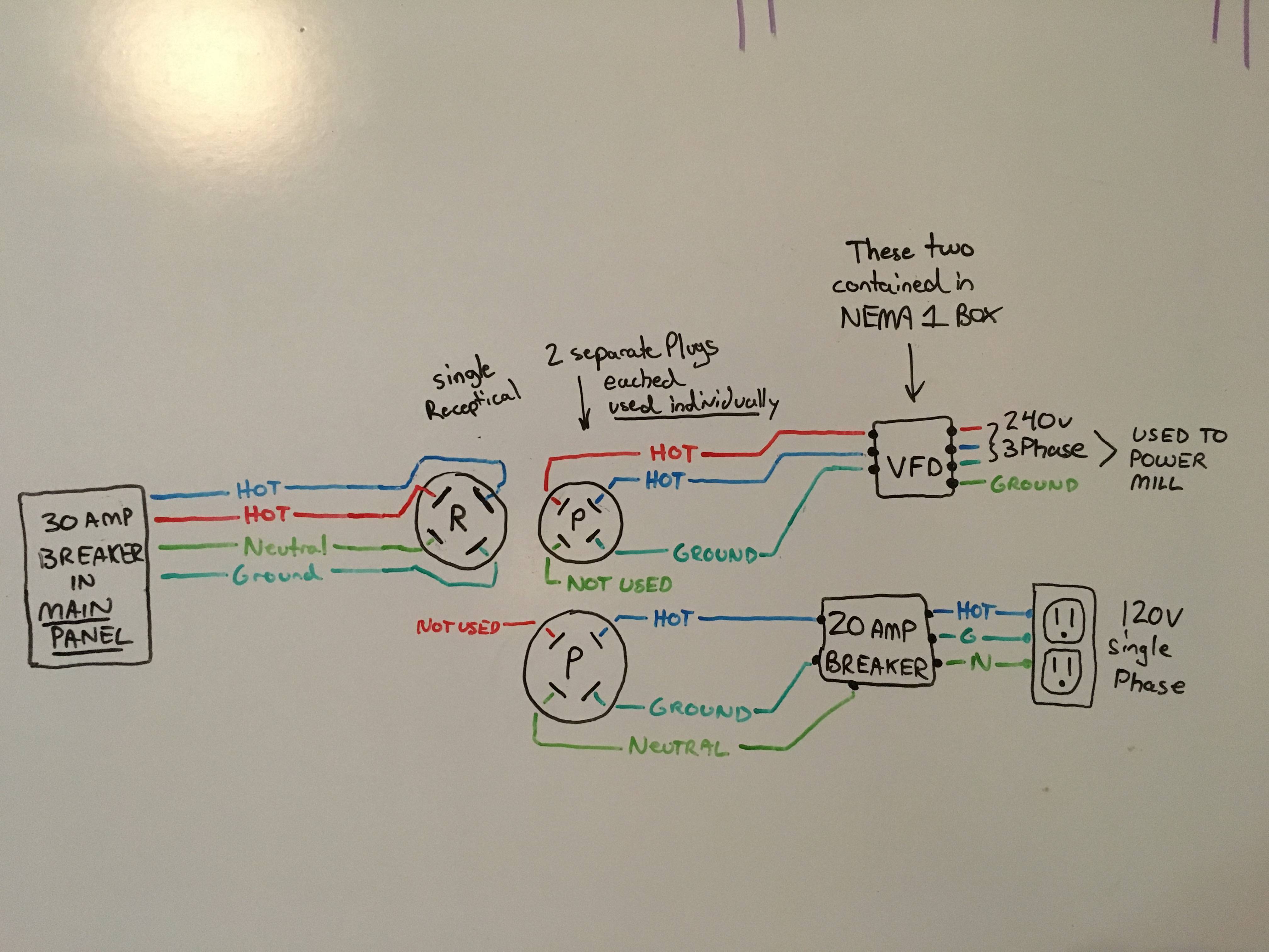
Obtener 120v monofásico y 240v trifásico fuera de receptáculo
