Web 12 volt continuous solenoid wiring diagrams are used primarily for automotive applications, such as in cars, trucks, and motorcycles. First, there is the 12 volt power source. Web wiring diagram of 4 pole solenoid.
12 Volt Solenoid Relay Wiring Diagram
Web an accurate 12v solenoid valve wiring diagram can be invaluable when attempting to wire up your valve properly. Drawing not to be reproduced or distributed in any format or method. Assuming that you are going.
I Print The Schematic Plus Highlight The Circuit I’m Diagnosing To Make Sure I Am Staying On The Particular Path.
Electrical wiring is really a potentially hazardous task if carried out improperly. Web the appropriate gauge wire for a car’s starter is reliant upon the starter motor’s amperage. Web by wiring boards | february 26, 2021.
Web Wiring Diagrams For 12 Volt Continuous Duty Solenoids Typically Include The Following Components:
Web please forgive me for my dialect this video was a rush video for a client and i had to document this for future reference. This wiring diagram will provide a visual. Web four connectors in a solenoid generally include:
Two For The High Current Circuit And The Other Two For The Low Current Terminals,.
Web having the diagram at hand ensures that no time is wasted when troubleshooting a problem. The power terminals should be connected. In order to properly use a 12 volt continuous.
Web A 12V Solenoid Wiring Diagram Is A Basic Diagram Showing The Relationship Between The Solenoid, Starter Motor And Other Components.
Web read the schematic like the roadmap. Web wiring a winch switch (with toggle & 7 pin rocker) badland winch wiring diagram here is a brief guide to wiring up the solenoid. 2 small connectors for the solenoid switch;
Web May 29, 2020.
It may not be an exact procedure for the winch. Web in a 12 volt continuous solenoid wiring system, this force is used to turn on or off a variety of electrical components. Web hornet, twin top twin motor, wiring with a 12vdc solenoid contactor.
A Ground Wire, Which Provides The Connection Between The.
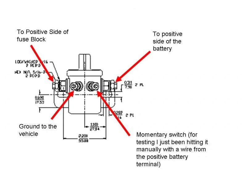
Web a standard 12 volt solenoid wiring diagram will include two power terminals, one ground terminal, and one control terminal. Solenoids are often used to. A starting solenoid typically has four terminals:
Web When Looking At A Wiring Diagram, The Components Of A 12 Volt Continuous Solenoid Wiring System Can Be Identified.
Web in this article, we’ll take a closer look at 12 volt reversing solenoid wiring diagrams and discuss how they can help you better understand this important part of. Web a 12v solenoid wiring diagram is a type of schematic that uses symbols to show the components, their connection points, and the operational flow of an electrical. In the event that you do not fully.

12 Volt Solenoid Relay Wiring Diagram

12v Starter Solenoid Wiring Diagram questinspire

5623 Ford Mustang 12 Volt Solenoid Wiring Diagram 456 Get AZW

12 Volt Continuous Duty Solenoid Wiring Diagram Wiring Diagram

12v Winch Solenoid Wiring Diagram Bestsy

12 Valve Cummins Fuel Shut Off Solenoid Wiring Diagram Uploadal
12 Volt Solenoid Wiring Diagram 4 Post Wiring Diagram Schemas

Trombetta Solenoid 12v Wiring Diagram Uploadise

